Powering the London Underground: over 100 years of change
Introduction
The London Underground is one of the world’s oldest and most intensively used metro systems. Since its first line opened in 1863, it has evolved into a complex network carrying millions of passengers every day. Behind this operation lies a robust and carefully engineered electrical power system, designed to deliver reliable traction power to hundreds of trains while meeting strict safety and efficiency standards.
This article explores the technical foundations of the Underground’s power supply, including its historical development, voltage standards, rail configuration, traction ratings, substations, and modern AC–DC conversion systems.
Historical development of the London Underground’s power supply
The earliest Underground lines were operated by steam locomotives, which caused severe ventilation and air quality problems. Carriages were constructed from wood and illuminated by gas, reflecting the technological limitations of the time. By the late nineteenth century, electrification had become a necessity rather than a convenience.
The City & South London Railway, constructed from 1886 and opened in 1890, was the first deep-level electric tube railway. It initially adopted a 500 V DC traction system supplied via a third rail. By the early twentieth century, most Underground lines had converted to electric traction, and London Underground began developing its own power generation infrastructure.
Lots Road Power Station
Lots Road Power Station in Chelsea was commissioned in 1905 to supply the District Line and later much of the wider network. Its original installation consisted of eight 5.5 MW Westinghouse turbo-alternators operating at 11 kV and 33.5 Hz, supported by coal-fired boilers.
Over time, the station underwent extensive modernisation. Early equipment was replaced by larger Parsons generators, and capacity was progressively increased. By the early 1930s, installed capacity exceeded 100 MW. Later conversions included oil firing and, in the 1970s, natural gas operation. As grid electricity became cheaper and more reliable, Lots Road was relegated to standby service and finally closed in 2001.
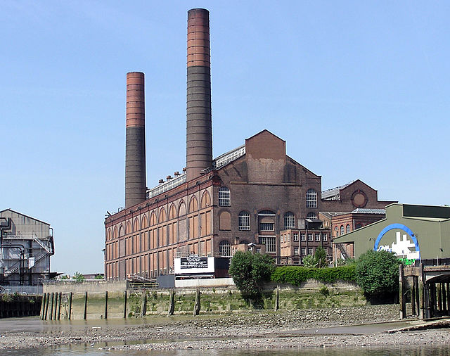 Figure 1. Lots Road Power Station.
Greenwich Power Station
Greenwich Power Station was commissioned in 1906 to support London’s tramway system and later the Underground. It initially employed steam engines driving alternators, before being upgraded with turbo-alternators. In the 1960s, these were replaced with Rolls-Royce gas turbine generators, giving a total capacity of approximately 118 MW.
Unlike Lots Road, Greenwich remains operational as an emergency power facility, providing resilience in the event of major supply failures.
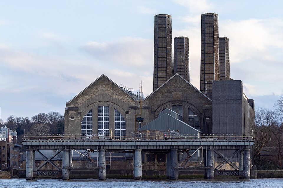 Figure 2. Greenwich Power Station building north face.
Neasden Power Station
Neasden was the smallest of the early Underground power stations. Commissioned in 1904, it initially operated with 3.5 MW turbo-alternators and later expanded with larger units. By the 1950s, its capacity approached 90 MW. The station ceased operation in 1968 as grid supply became dominant.
Present-day power supply architecture
Today, the London Underground draws electricity from the National Grid at eight bulk supply points, typically at 22 or 33 kV. Power is distributed through a dedicated network comprising around 270 substations across approximately 250 miles of track.
This infrastructure includes high-voltage cables, transformers, circuit breakers, battery systems, frequency changers, and communication equipment. Together, these assets form a highly resilient network capable of supporting dense urban operations.
Four-rail system
Unlike most metro systems, which use a single conductor rail and return current through the running rails, the London Underground employs a four-rail DC system.
Table 1. Parameters associated with the London Underground's four-rail system.
| Rail Type | Typical Voltage |
|---|---|
| Positive rail | +420 V DC |
| Negative rail | −210 V DC |
| Running rails | ~0 V DC |
| Nominal supply | 630 V DC |
The four-rail arrangement was adopted to minimise stray current and reduce corrosion of tunnel linings and nearby infrastructure. By preventing significant traction currents from flowing through the running rails, the system limits electrolytic damage and improves long-term structural integrity.
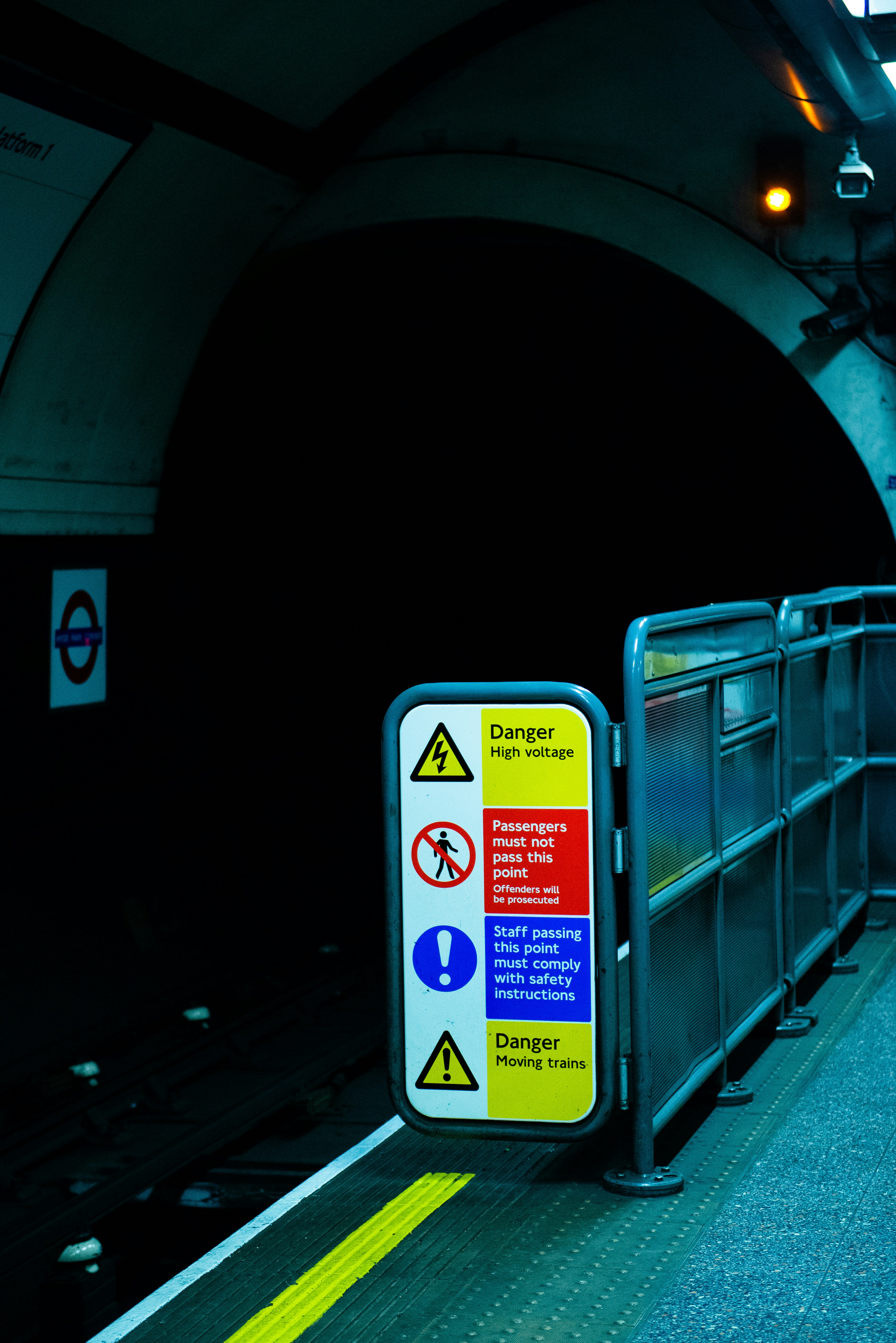 Figure 3. Underground warning signs.
Traction substations and conversion
Traction substations convert medium-voltage AC into DC for train operation. They are generally spaced at intervals of multiple kilometres and contain step-down transformers, rectifier units, DC switchgear, and protection equipment. Output voltage is regulated to maintain approximately 630 V under varying load conditions.
Early conversion systems relied on rotary converters and motor-generator sets. Although effective, these machines were bulky, inefficient, and maintenance-intensive. From the 1930s, mercury arc rectifiers offered improved performance but introduced environmental and safety challenges.
Modern substations employ solid-state rectifiers based on silicon diodes, thyristors, and increasingly IGBT technology. These systems provide high efficiency, compact design, and advanced remote monitoring capabilities, with conversion efficiencies typically exceeding 95%.
Rolling stock onboard equipment
Modern Underground trains use distributed traction systems with multiple powered axles, power electronics and regenerative braking.
Table 2. Parameters associated with the London Underground's rolling stock.
| Parameter | Typical Value |
|---|---|
| Supply voltage | 630 V DC |
| Traction power | Up to 2.5 MW |
| Motor type | AC induction or permanent magnet synchronous machines |
Traction drive architecture
Each train includes input protection and filtering, a DC link, variable frequency variable voltage inverters, traction motors, and auxiliary converters. The inverter converts the DC supply into variable-frequency AC, enabling precise control of speed and torque.
Regenerative braking
During braking, traction motors operate as generators, converting kinetic energy into electrical energy. This energy is returned to the DC supply and can be absorbed by nearby accelerating trains or station loads.
TfL estimates that regenerative braking recovers 26% of traction demand (130 GWh per year) while also lowering tunnel heat levels.
Resilience
Given the scale of operations, reliability is a fundamental design requirement. The network employs multiple grid supply points, ring-fed distribution systems, parallel substations, automatic load transfer schemes, and standby transformers. These measures enable most faults to be managed without major service disruption. Innovation programmes focus on improving energy efficiency, resilience, and sustainability. Key initiatives include upgraded substations, expanded energy storage, wider adoption of permanent magnet motors, smart grid integration, and increased use of low-carbon electricity.
Conclusion
The power system of the London Underground reflects more than a century of engineering evolution. From steam traction and in-house power stations to advanced semiconductor converters and regenerative braking, it demonstrates continuous adaptation to rising demand and technological change.
Its distinctive four-rail DC system, dense substation network, and highly redundant architecture enable reliable operation in one of the world’s busiest urban environments. For power and railway engineers, it remains a compelling case study in large-scale traction power engineering.